Geekworm Smart
Fan and Power Expansion Board
Note: Your fan HAT may or may not be a “Geekworm” as they
seem to be made under different names. I read many articles that state that the Raspberry Pi does
not require a cooling fan as the board is designed to handle temperatures in
the 70ºC range and will throttle the CPU/GPU to reduce the heat if required.
But, personally, I still like to use heat sinks and fans and keep the
temperature down even if it won’t do any actual damage. Besides, it was a
good project to refresh my math skills.
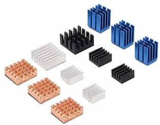
I will assume that at this point you should have some
basic knowledge about heatsinks and cases. There are many different types of
heatsinks available to you should you decide to use one. Not only do they
come made of different materials (copper, aluminum, etc) but they come in
different sizes. The number, size and type is up to you to research and also
depends on the model of your Raspberry Pi. Keep in mind that if you are going
to install a heatsink then the placement of your fan will also be important
and the available space for these components must be considered. If you are
using a case then it may or may not have slots or mounting mounts for a fan.
You may have to make some modifications to the case yourself. Some people
claim that the method you use to attach the heatsink to the chip can actually
increase the temperature. I will let you do your own research, but the short
version is that you should use a proper thermal adhesive if you use a
heatsink.
I spent many hours reading all about fans and various ways
to control them, or not. Some solutions are quite simple and are literally a
5V 0.2A fan plugged into the GPIO pins for +5V and GND. There are even water
cooled and mineral oil cooled solutions. I won’t go into those.
Basic 5V fan. This option has some obvious benefits, and
obvious drawbacks. Benefit: can’t get much simpler. Drawbacks: No control.
The fan runs at maximum speed all the time. These little fans can be quite
noisy at high speed so this is not ideal if you plan or being anywhere near
it. You could splice an on/off switch into the wiring and mount it in your
case to provide some basic control. Some people suggest that using a 12V fan
and supplying only 5V will result in a quieter solution as the fan will not
run at full speed. However, the fan may not run at all either, depending on
your power supply and the fan.
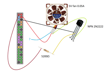
The Raspberry Pi can provide something called Pulse Width
Modulation, or PWM. Essentially this is a way to send a signal to your device
(fan, LED, etc) that quickly pulses the power on and off to allow you to
control the “strength” in a sense. This can be used to control the brightness
of an LED or the speed of a fan. This diagram shows the use of a transistor
and resistor to safely provide speed control to the fan. There are many other
examples using various fans, transistors, resistors and other components but
the basic principal is the same. By adding a couple of basic components, you
end up with a simple and inexpensive hardware solution. But, that is only
half of the overall solution. You need a software component (script) to set /
control the PWM value to turn the fan on, off, or to a specific speed. More
on that later.
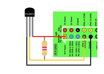
By adding a temperature sensor such as the DS1820, DHT11,
DHT22 or one of many others, you can monitor the temperature of a specific component
or generally within the case. With a script you can then set an appropriate
fan speed to balance noise levels with the temperature control. Note that the Raspberry Pi does allow you to monitor the
CPU and GPU temperatures WITHOUT adding any additional sensors.
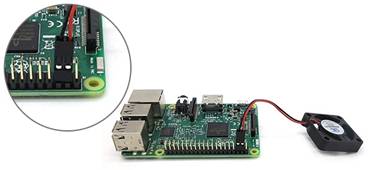
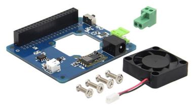
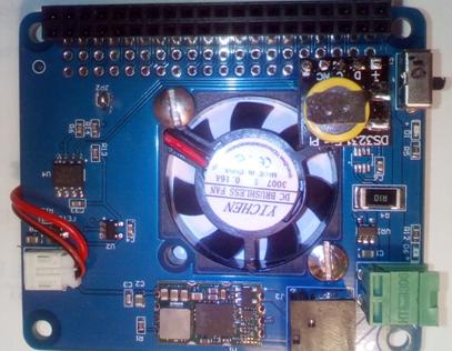
This HAT comes as a simple kit and all that is really required
is to mount the fan using the bolts. All the parts shown here came with the
kit I purchased. Because I have some relatively tall heatsinks that I like to
use, I chose to install the fan on the opposite side of the HAT than it is
typically mounted. To facilitate the wiring I cut a small slot into the
unused portion of the PCB on the side of the opening for fan near the fan
power connector. I also had to trim some of the power switch plastic slider
as it was too long by about 1mm to fit in my case.
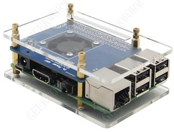
The full version of this kit includes a “case”, which is
really just a couple plastic plates and brass standoffs. This image shows the
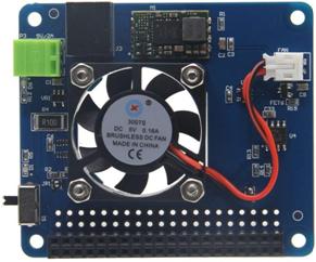
“standard” mounting of the fan and placement on the GPIO pins. More images and sample code can be found on this web site: http://www.raspberrypiwiki.com/index.php/Smart_Fan_and_Power_Expansion_Board The last bit that I will discuss briefly in relation to
this HAT compared to some others is that it does NOT have a real time clock
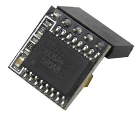
(RTC) module or battery. At one point there was a product called the
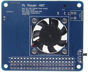
PiCoolFan which seemed ideal. It was a small board (see image) that included
a temperature sensor, PWM fan control and RTC. I have as yet been unable to
determine its suitability for use with the RPi3B+ and it seems it may have
been replaced by another product which does not include a RTC. In any case,
one thing I like about the Pi Power Hat is that it includes access to the
GPIO pins so I could add my own RTC quite easily. Enough about the hardware, let’s get scripting! Almost all the PWM fan control scripts I could find were
pretty basic. At best, most seemed to provide an incremental speed control
based on temperature ranges and fixed increments. I was after something
better than 0, 25, 50 75 or 100% fan speed control and something more
flexible and dynamic. As an example, most scripts would use the logic
equivalent to: If the temperature is above 40 but lower than 50 then set the
fan speed to 25%. Using these scripts as a starting point I wrote my own
script that should be easily configurable to match most installations. The script uses a couple different methods to query the
Raspberry Pi internal CPU temperature sensor. The modular design of the
script allows for the easy addition of other methods such as querying I2C
sensors (such as the one included on this HAT) although I consider the
onboard CPU temperature to be the one I am most interested in. In the configuration
settings within the script you can set the minimum temperature at which you
want the fan to start thus allowing the fan to be off, if desired, at lower
temperatures so that there is no noise. You also configure a temperature
above which the fan will run at its full capacity to provide maximum cooling. A calibration script should be run on each Raspberry Pi
with each specific fan to determine the minimum value for the PWM at which
the fan will actually begin to turn (although you could configure a reasonable
“guess” as this is only used as a base starting point). A maximum PWM value
can also be configured so that the fan will max out at 100% or whatever value
you set thus enabling you set only run at a speed at which the fan noise is
appropriate for you. The script will use the configured temperature range and
the configured PWM values to automatically determine the fan speed. Actual
real-time percentages are used rather than a fixed scale. For example, if it
is determined that the actual temperature is 15% of the way between the
minimum and maximum values, then the fan will be set to run at 15% of the
maximum rate configured in the script. While this may be overkill, it was relatively simple to
calculate a dynamic fan speed based on the temperature. The time between each sampling of the current temperature
can be configured as well. As the script runs under Python, which carries
some overhead, you don’t want to sample too often or the script itself will
cause the CPU temperature to rise. Generally speaking, sampling the
temperature once every 3-5 seconds is often enough without putting additional
load on the CPU. In many cases sampling every 10 or 30 seconds would even be
sufficient. The script is designed to run as a background task but
there are 2 diagnostic options that can be enabled. A real-time output can be
displayed to the console (telnet or SSH shell) and optionally be redirect
through a standard pipe to a file for logging purposes. Also, the last loop
iteration can be enabled to be logged to a file making it easy to see at a
glance though shell access, a web site or file share what the last
temperature and fan settings were. These optional diagnostics can be
individually disabled or enabled. |


Update September 28th, 2018
Ok, so one thing that I
didn’t like was the issue that I have always liked having a Real Time Clock
(RTC) installed. In the past I’ve tried them all, DS1302, DS1307, etc and made
lots of little add-on boards with batteries. I ended buying a bunch of the
DS3231 modules as they were small, simple to install and used a super-cap to
maintain the time.

The issue then became
installation. The fan HAT obviously blocked the GPIO header. Idea! Remove the
header from the DS3231 module and use the blank header on the fan HAT to
install the module.
I’ve also been playing with
the temperature sensor on the HAT. It turns out it is a LM75 chip (8-pin chip
just above the fan power connector). This is great as both the LM75 and the
DS3231 use the I2C bus but default to different addresses. Also, a quick mention
that the on-off switch does work, if you use the power connector on the HAT.
Slide it towards the GPIO header to turn on the power, and slide it towards the
middle of the HAT to turn it off. I couldn’t find this posted anywhere and
although fairly obvious, I wanted to make mention of it. You may also notice that I installed the fan on the opposite side than intended. I did this to make more room for the heatsinks and RTC module. There is just enough space in the case I used for a slim fan.
More details and examples of
how to use the LM75 will be posted in the sample scripts.